Touchless faucets look straightforward to end users, but the performance they feel is the result of sensing physics, signal processing, valve mechanics, and sink-area geometry. This guide explains measurable definitions and field-ready mitigation steps for commercial restrooms.
In commercial restrooms, that system has to work under bright lighting, reflective finishes, cross traffic, wet hands, and varying water pressure. When the system is not tuned to the environment, three problems dominate complaints and service calls:
- Activation window issues: the faucet does not respond when hands are placed where users expect, or it triggers from an unexpected spot.
- Latency: the faucet responds, but it feels slow enough that users wave repeatedly.
- False triggers: water turns on when nobody intends to use the faucet.
For AEC teams, these issues are not simply “product quality.” They are system outcomes influenced by layout, materials, power planning, commissioning steps, and how performance is specified. This article explains what these terms mean in measurable, field ready ways, and provides practical mitigation strategies you can apply during design and closeout.
Sensor faucet performance is a stack, not a single specification
A sensor faucet is best understood as a layered system:
- Emitter and receiver
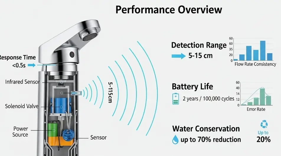
Most commercial faucets use infrared (IR) emission and detection. Some use dual sensing or additional logic to improve confidence. - Signal processing
The controller filters noise, rejects ambient interference, and decides whether a return signal matches a “hand present” pattern. - Control logic
Timers, auto shutoff, run on delay, lockouts, and “debounce” logic shape user experience. - Actuation
The solenoid valve opening speed and consistency directly affect perceived responsiveness. - Hydraulics
Water pressure, aerator selection, debris screens, check valves, and piping configuration influence flow stability and splash. - Power
Battery, transformer, or hybrid configurations change available actuation energy and response consistency.
A common field mistake is trying to “fix” a performance problem by adjusting sensitivity only. If the root cause is reflection, cross traffic, sunlight, or unstable hydraulics, sensitivity changes often trade one problem for another.
Activation window: define it like a detection zone
What the activation window actually is
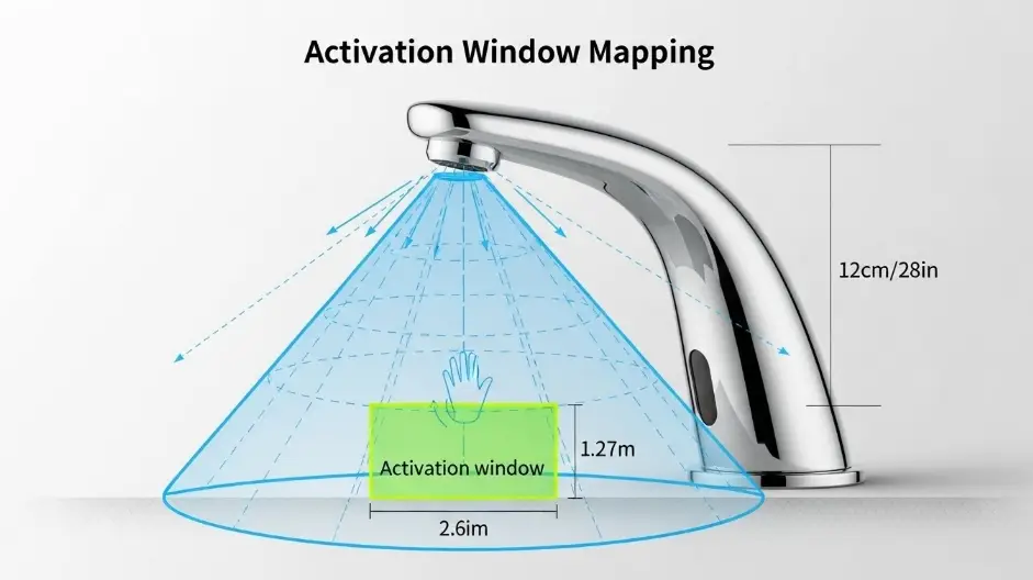
The activation window is the three dimensional detection volume in which a hand is reliably detected. It is not just a single distance. It is shaped by:
- Sensor lens geometry and aiming angle
- Background reflectivity in the sensor’s field of view
- Basin depth and rim profile
- Countertop material and finish
- Ambient light conditions, especially direct sunlight
- Water droplets and film on the sensor window
From a design perspective, the activation window should align with where hands naturally go for rinsing: roughly centered below the spout outlet, not too far forward and not so close that sleeves and objects trigger it unintentionally.
Why activation windows fail in real restrooms
Activation issues typically show up as one of these patterns:
- The window is too short: users place hands in the basin, but the sensor expects them closer to the spout.
- The window is too wide: movement in adjacent lanes or reflections cause unintended activation.
- The window is shifted: the sensing volume is not centered on the spout centerline because of installation angle, backsplash geometry, or reflective surfaces.
Field mapping method: a practical commissioning check
You can map the activation window with minimal tools. The goal is to convert “it seems okay” into a repeatable envelope.
Method
- Place painter’s tape on the counter aligned with the spout centerline.
- Mark distances from the outlet (or sensor face if that is the reference used by the manufacturer): 2 in, 4 in, 6 in, 8 in, 10 in, 12 in.
- At each distance, move a hand slowly upward and downward, then slightly side to side.
- Record outcomes: triggers reliably, triggers intermittently, does not trigger.
- Repeat once with wet hands and once with a dark sleeve or glove near the sensor.
Target activation windows by application type
These are not universal numbers, but they are useful design intent references and can help you evaluate submittals against real geometry.
| Application context | Typical stable depth range | Design notes |
|---|---|---|
| Standard commercial lavatory | 3 to 7 in | Ensure spout reach places rinse zone within sensing volume. |
| High traffic public restrooms | 3 to 6 in | Favor stable zone over maximum distance to reduce nuisance triggers. |
| Corrections and high vandal risk | 2 to 5 in | Tight window plus strong lockout logic reduces water waste. |
| Healthcare and clinical | 4 to 8 in | Validate detection with wet hands and sleeves, prioritize consistency. |
| Child heavy environments | 2 to 6 in | Consider sensor angle and spout height relative to user reach. |
If you see marketing language like “0 to 12 inches,” treat it as a broad capability statement, not a guarantee that the zone is stable in reflective and high traffic conditions.
Latency: measure it and break it down
Latency is the time from “hands enter the activation window” to “water is available in a stable stream.” Users interpret latency as malfunction even when the faucet is technically working.
Latency is usually a sum of components
Latency often includes:
- Sensor sampling interval: how frequently the system checks for a valid return signal
- Debounce time: a confirmation period used to avoid false triggers
- Valve opening time: solenoid and mechanism response
- Hydraulic stabilization: the time it takes for flow to become steady at the outlet
If a faucet feels slow, it is useful to know whether the delay is in detection logic or in valve hydraulics.
Simple onsite latency test
- Use a smartphone slow motion video mode if available.
- Frame both the hand movement and the outlet.
- Count frames from first entry into the activation zone to first continuous flow.
Practical targets
- Under about 250 ms to first flow feels highly responsive.
- 250 to 600 ms often feels acceptable in commercial settings.
- Beyond 600 ms, users tend to wave or pull hands away and re enter, which can create stop start behavior and increase false triggers.
The latency and false trigger tradeoff
Many controllers lengthen debounce time to reject noise. That reduces false triggers but increases perceived delay. The best outcome is not maximum sensitivity or minimum debounce. The best outcome is a sensing configuration that reaches confidence quickly in the real environment.
False triggers: typical causes and what they look like
False triggers are often blamed on “bad sensors,” but the environment is frequently the driver.
A) Cross traffic and adjacent movement
People walking past the lavatory can enter the edge of the sensing volume, especially when sinks are close to circulation paths.
Mitigations
- Use partitions or side panels to block lateral movement signals.
- Align sink banks so circulation paths do not pass directly behind the sensing area.
- Favor a narrower lateral activation profile over maximum distance.
B) Reflections from glossy or specular surfaces
Mirrors, polished stone, chrome accessories, and glass partitions can reflect IR signals or create confusing returns.
Mitigations
- Avoid mirror edges or glossy trim directly within the sensor field of view.
- Prefer finishes in the detection area that reduce specular reflection.
- Adjust sensor aim or select models with better ambient and reflection rejection.
C) Sunlight and high ambient IR
Direct sunlight can overwhelm IR receivers or shift the effective threshold.
Mitigations
- During design, note restroom locations with direct daylight exposure.
- Plan shading, films, or lighting design that avoids direct IR glare into the sensor.
- Validate performance during peak sunlight hours, not only during nighttime commissioning.
D) Water droplets and sensor window contamination
Splashing, mist, and grime can scatter IR and create unstable detection.
Mitigations
- Ensure aerator and flow control selection minimizes splash.
- Include sensor window cleaning as part of facilities SOP.
- After construction, clean sensor windows to remove haze from dust, grout, and sealants.
E) Electrical noise and power issues
Hardwired units can experience noise or voltage drop, especially with long low voltage runs or shared transformers.
Mitigations
- Follow transformer distance and wire gauge recommendations.
- Provide clean grounding and bonding.
- Avoid loading a single transformer beyond manufacturer limits.

Design and commissioning strategies that hold up in the field
Strategy 1: Solve with geometry before software
If you can reduce false triggers by preventing unwanted motion from entering the detection zone, do that. Physical layout solutions remain stable over time, while sensitivity settings often drift with changing conditions.
Examples
- Add side partitions to block cross traffic signals.
- Avoid placing reflective accessories directly in the sensor line of sight.
- Ensure spout reach positions the rinse zone within the stable detection envelope.
Strategy 2: Specify performance, not just product type
A spec that only says “sensor faucet” invites wide variation in experience. Instead, include measurable requirements tied to commissioning.
- Activation window must be stable within the intended hand rinse zone for the basin and spout geometry used.
- Latency target range under typical ambient lighting.
- False trigger tolerance, such as no nuisance activation during an observation period under normal circulation conditions.
- Adjustable settings or factory tuning suitable for commercial environments.
Strategy 3: Commission with a repeatable checklist
A short checklist can prevent months of callbacks.
- Map detection zone at multiple distances, record stable range.
- Verify latency with a quick video test, document typical response.
- Observe for false triggers for 5 minutes with normal cross traffic.
- Confirm shutoff behavior and any run on delay.
- Confirm auto shutoff timer and any lockout logic for water saving and safety.
Strategy 4: Align flow rate, splash control, and detection stability
Flow influences splash, and splash can create sensor window wetting and nuisance triggers. Water efficiency programs and code limits also shape flow choices.

If a faucet is WaterSense labeled or designed to meet comparable limits, that typically points to flow rates intended to balance water use and usability. In practice, a stable, low splash stream can improve sensor stability by keeping the sensing face cleaner and drier.
Recommended mitigation tactics by symptom
This matrix helps facilities teams and commissioning agents diagnose quickly without trial and error.
| Symptom | Likely cause | First action | Second action |
|---|---|---|---|
| Faucet feels unresponsive | Window too short or misaligned | Map the detection zone | Adjust aim or sensitivity, check reflective background |
| Faucet activates but feels slow | Debounce high or valve slow | Measure latency by video | Check power mode, solenoid condition, pressure stability |
| Faucet turns on when people walk past | Cross traffic in detection volume | Add side partitions, adjust orientation | Narrow activation window through settings |
| Faucet chatters on and off | Splash wetting sensor window or unstable returns | Reduce splash by flow control and aerator | Clean sensor face, add lockout or adjust filtering |
| Works at night, fails in daytime | Sunlight or high ambient IR | Test at peak daylight | Add shading, relocate sink bank, select improved ambient rejection |
Sample specification language you can adapt
This is performance based language intended to remain non proprietary while setting clear expectations.
General performance
- Provide sensor operated lavatory faucets suitable for continuous commercial duty.
- Activation window must provide reliable detection within the intended hand wash zone for the specified basin and spout geometry.
- Initial activation latency shall meet the project performance target under typical ambient lighting conditions.
- Provide false trigger mitigation appropriate for commercial environments including ambient light rejection and signal filtering.
Accessibility
- Controls and operable parts in accessible toilet rooms shall meet applicable ADA requirements for operable parts and reach ranges.
Commissioning and closeout
- Provide manufacturer commissioning procedure and settings documentation.
- Contractor shall demonstrate activation window stability and false trigger performance at each installation and record settings in closeout documents.
Category pages for product context and technical reference
When you evaluate sensor performance, it helps to see how different commercial catalogs present sensor ranges, power options, and installation constraints. The links below are included as category level sources for your readers and spec teams.
Standards and support documents
These are useful support documents for AEC oriented readers who want standards context and water efficiency references.
Closing notes for AEC teams
Optimizing sensor performance is less about chasing perfect sensitivity and more about ensuring the sensing volume matches the wash zone, limiting the visual field that invites false triggers, and commissioning in real conditions. Activation window mapping and simple latency measurement can turn subjective user feedback into repeatable acceptance criteria. When you treat sensing as part of the restroom system, you reduce callbacks, improve user experience, and deliver predictable performance across an entire facility.

Location: Atlanta, GA
Profile: Facility planning expert focused on large-scale commercial installations. Works with developers to implement durable, vandal-resistant soap dispensing solutions in stadiums, transit hubs, and educational campuses.